WS2812B LED
WS2812B LED with an ESP8266 microcontroller and software in Python as well as C++
This software/hardware project incorporates an ESP8266 WiFi microchip with Python and Arduino IDE to individually address each LED light and create pretty cool light shows
I wanted to take a step away from all the actuarial math and statistical software and create an audio reactive visualizer that would respond to my guitar playing. At first I thought it was going to be a simple enough project that I could knock out in like a weekend or so.. Boy was I wrong. There was so much learning both on the software and hardware side though mainly hardware. I do not have an electrical engineering background though after completing this project I think that the veracity of that statement is no longer true. Okay so that being said without further to do I’m going to start with the necessary hardware components, then connections and then loading the software though I intend to present this information from a tutorial point of view.
Please send all inquiries, problems and comments to:
Email: trejo.juann@gmail.com
For the hardware aspect of the project you are going to need the following:
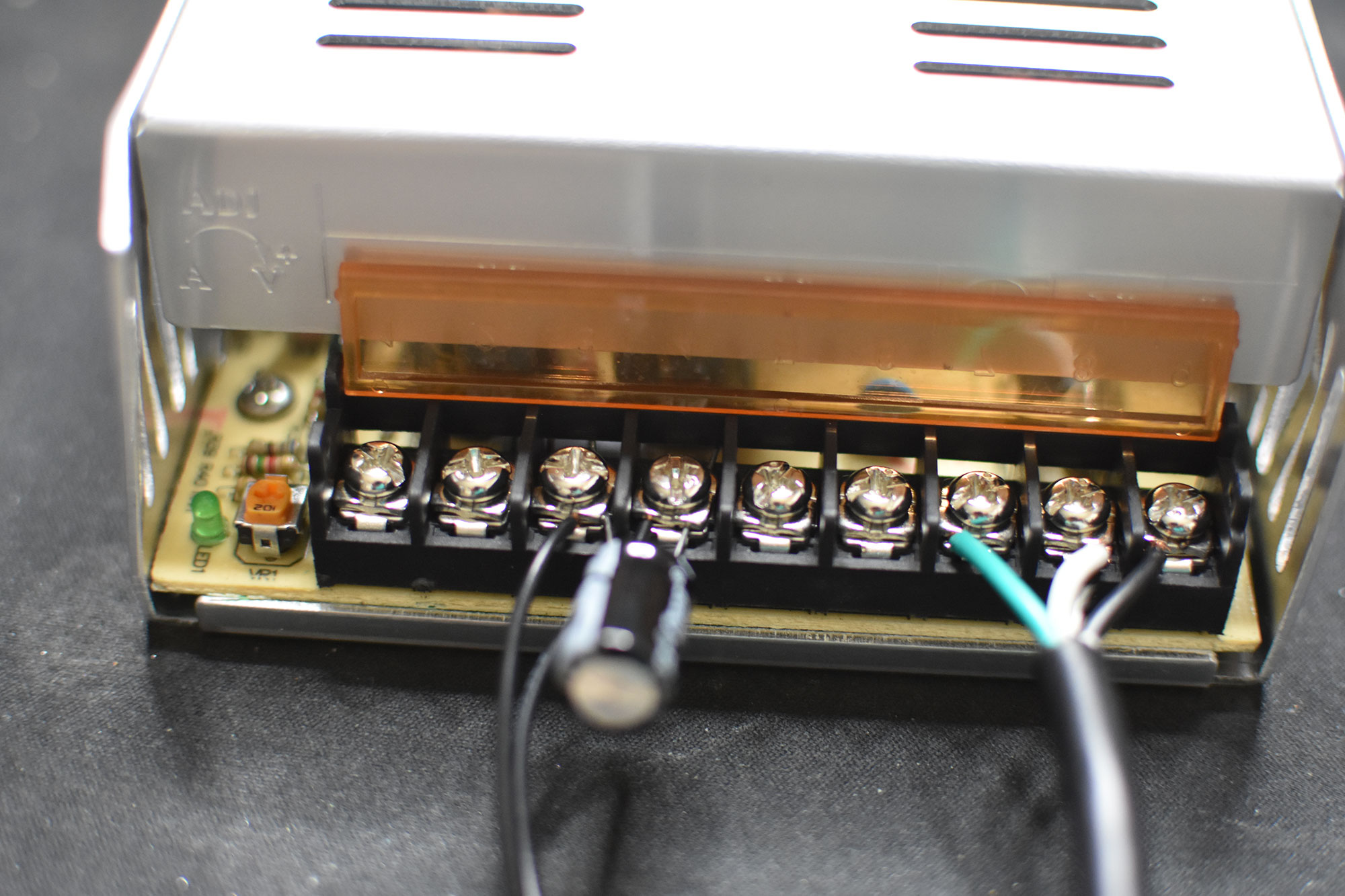
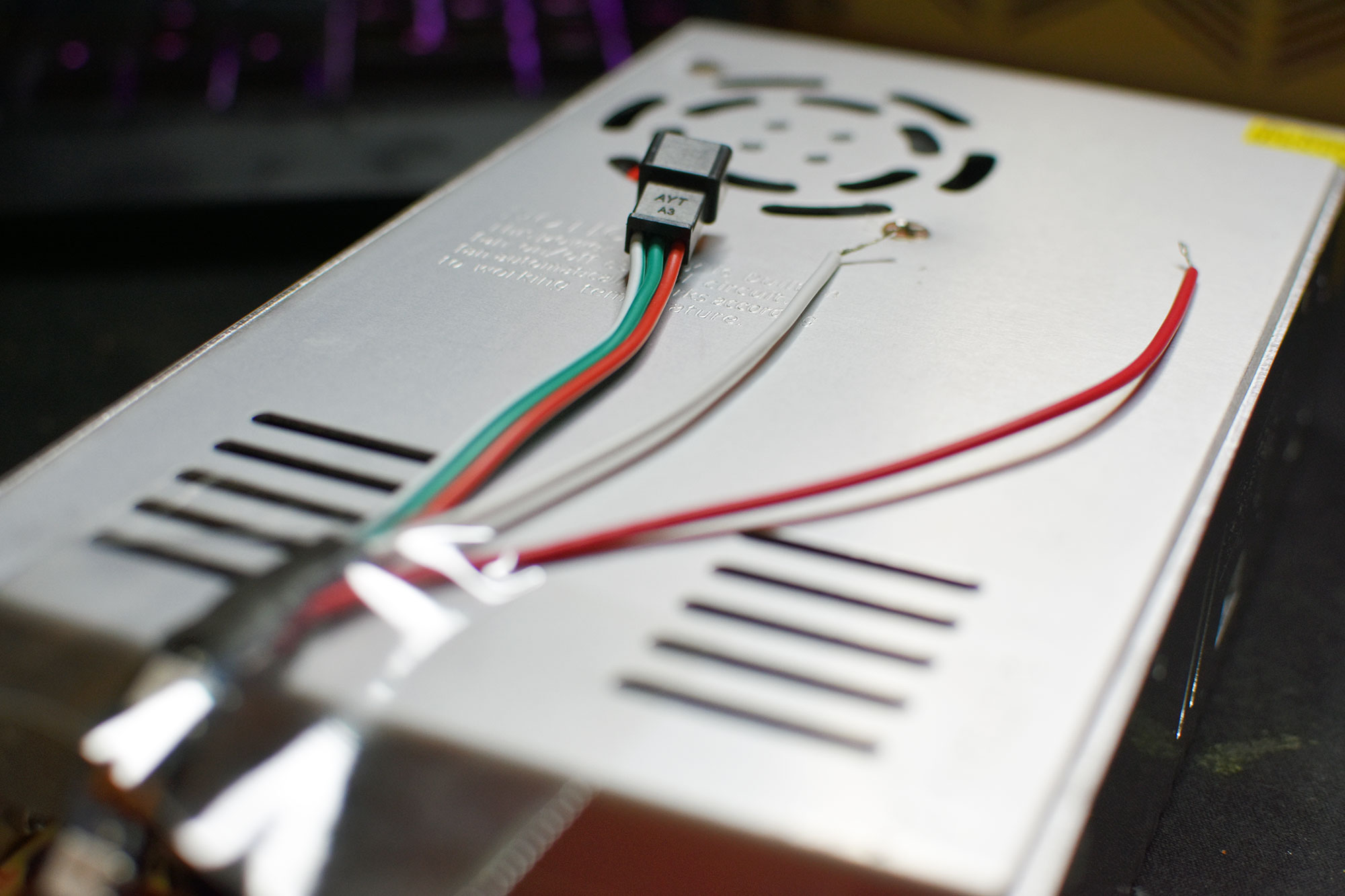
Firstly, we must provide power to power supply unit (PSU) we do so my stripping the standard power cable with the wire cutter and connecting white to the neutral connector (denoted by capital letter N), black to the positive connector (denoted by capital letter L), and the green wire to the ground connector (denoted by the perpendicular symbol, from geometry, with two parallel lines below it with each being shorter than the previous one). We set this aside for now.
Power cable connected to PSU
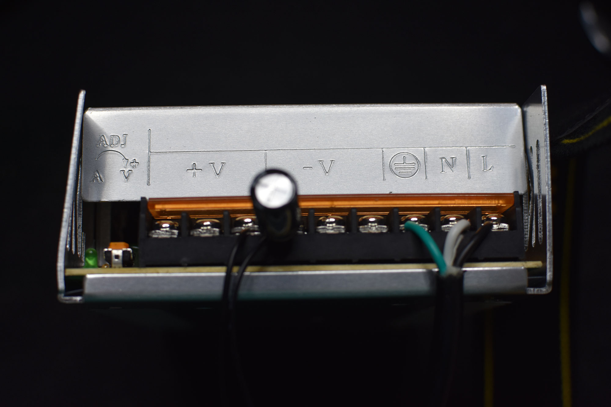
CLose up of power cable connected to PSU
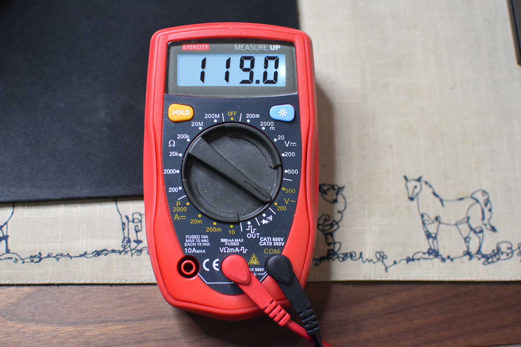
The typical NA outlet outputs up to 120V
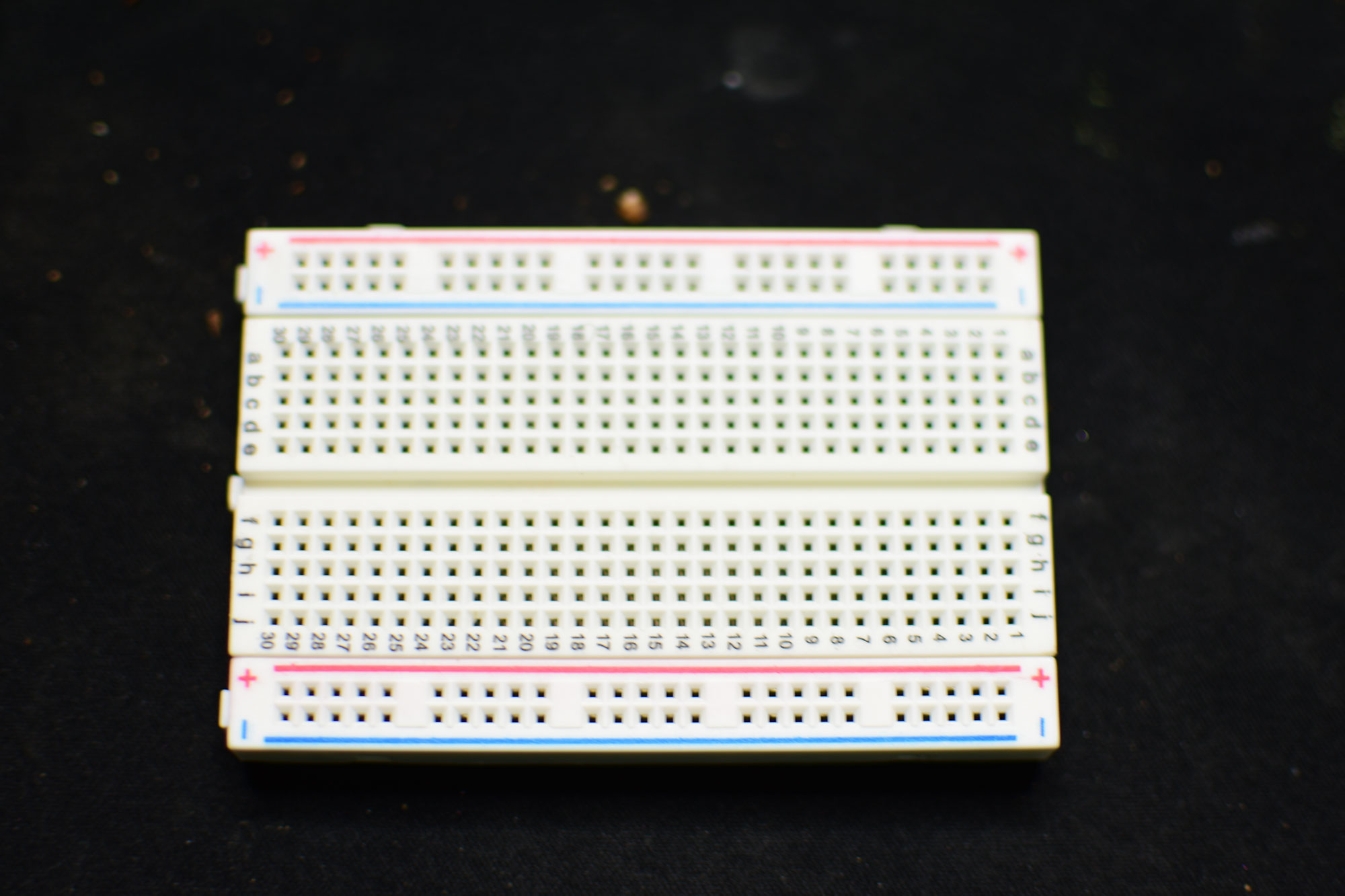
Next, we are going to connect the ESP8266 module and the logic level converter to the breadboard. I think the easiest way to explain the layout of the breadboard is compare it to an excel spreadsheet. Much like excel the horizontal axis consists of letters A-J and the vertical axis consists of numbers 1-30 (assuming you are using a mini breadboard and also assuming you have not activated the R1C1 mode of excel). A connection to say B5 will target any element connected to said row in this case row 5. The sides of the breadboard consist of two rails positive and negative to which current is connected to and drawn from and vice versa. The breadboard is vertically symmetrical (A-E mirror F-J). It does not matter where you connect the modules on the breadboard just ensure that the pins of each module touch both sides created by the “imaginary” line of symmetry between column E and F. In other words, make sure they bridge the breadboard gap (Mind the GAP!).
Solderless breadboard
Completed circuit
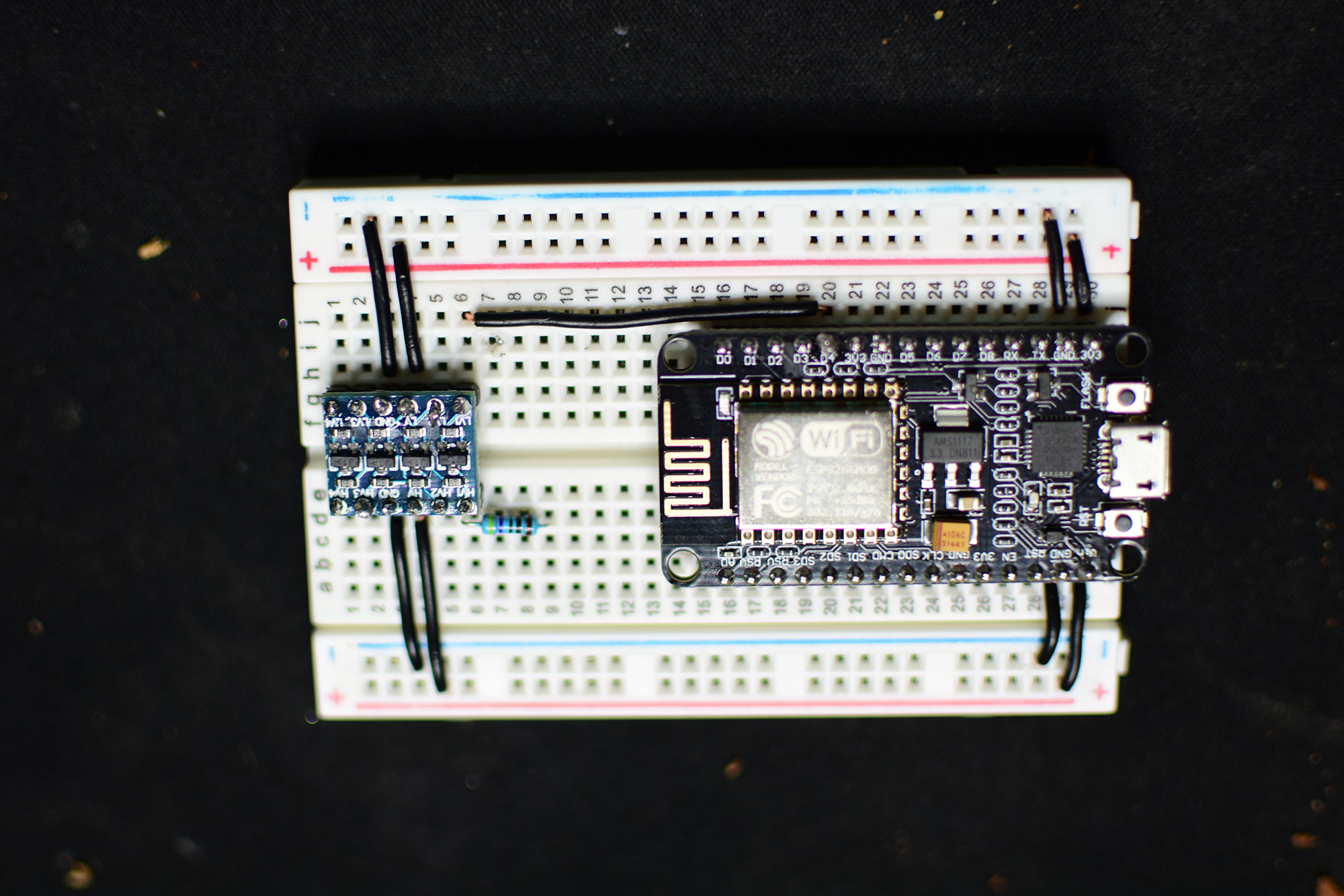
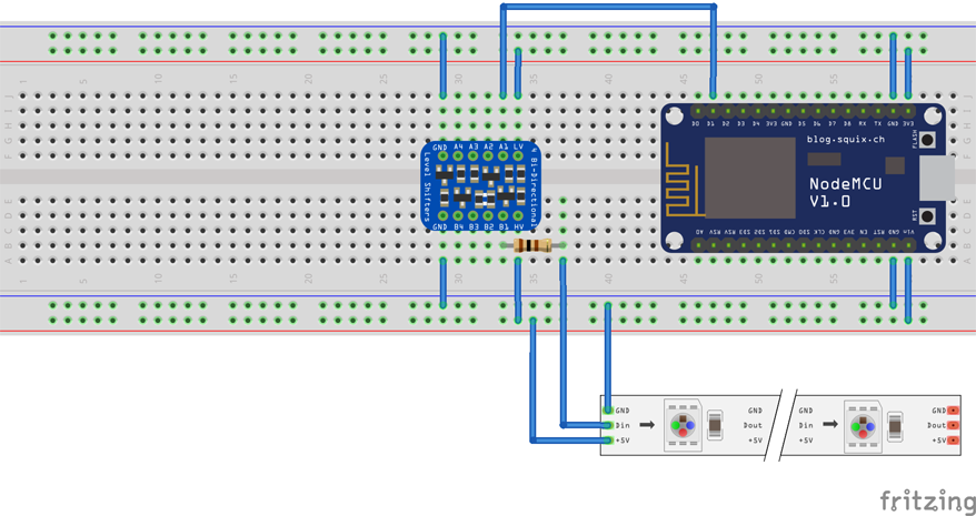
Diagram of circuit
However, we must first solder the pins to the logic level converter (assuming they’re not already connected). It’s easier to connect the pins to the breadboard then place the PCB (printed circuit board) of the logic level converter on top and then solder each pin rather than doing it separately and then connecting it to the breadboard (taking advantage of the fact that the breadboard will hold the PCB in place). The ESP8266 module comes already attached for us so simply connect that to the breadboard. Finally add the 470-ohm resistor to the first port of the logic level converter. We must add this resistor because the ESP8266 module is a 3.3V device and the LED lights expect the data signal to be 5V so we are essentially using it to force 5V and create a stable connection; though you may be able to get away without doing so however I was experiencing signal “noise” and this solved the problem. Again, this is dependent on the particular lights that you are using.
Okay so now we are ready to do some wiring. Everything we do from here on out will be connected to the breadboard. You can think of it much like the motherboard for a computer. We can power the ESP8266 with the standard micro USB cable but we are going to take advantage of our power supply unit and power it that way. Even though the ESP8266 is powered by a micro USB cable which delivers 5V it has a transformer built in that converts the current to 3.3V. So essentially, we must provide power to the ESP8266 module and the logic level converter and run the data cable through the converter and then out to the data port of the ESP8266 module. So, we connect the GND and 3V3 to the negative and positive terminals respectively for the ESP8266 and the logic level converter ensuring that we deliver power to the Vin side of the ESP8266 and HV (high voltage) side of the logic level converter.
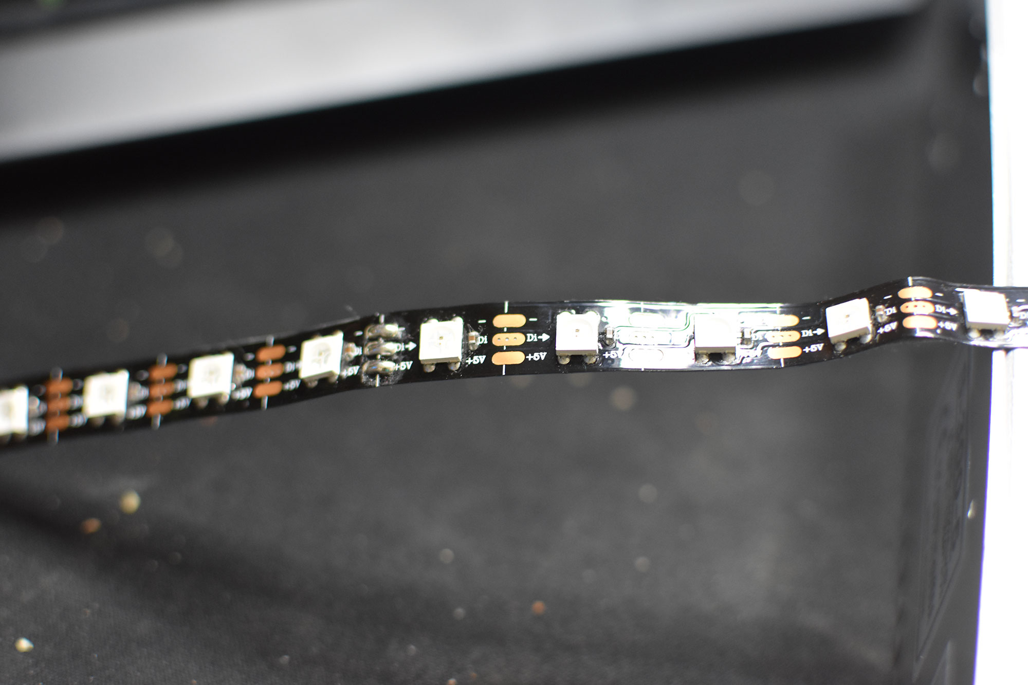
WS8212B lights notice the direction of Di it goes from left to right
red/white wires connect to PSU the others 3 to the breadboard
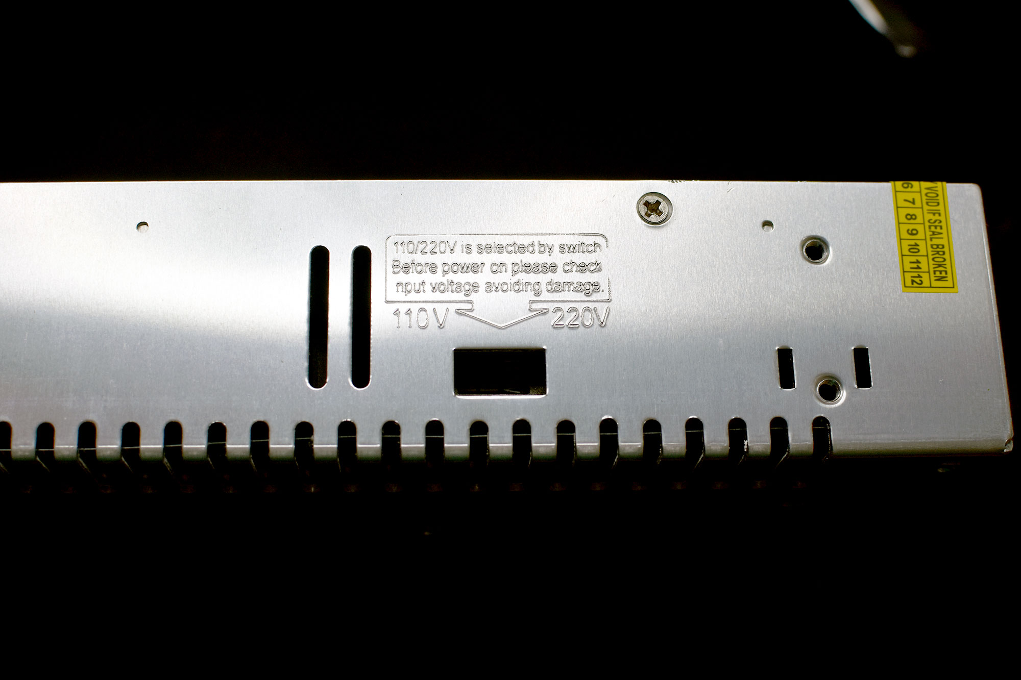
110V must be selected on the PSU (if you live in NA that is..)
Finally, we connect the LED lights positive and negative wire to the power supply but before doing so we are going to add an 1000uf 25V Capacitor to prevent any electrical surges to damage our first LED light. We do the same with the breadboard ensuring we power on the high voltage side that the logic level converter is attached to as well as the ESP8266 module. It does not matter which end you power the LED lights from as electricity flows in a circular matter (this is something that was mind blowing for me) however the data cable must follow the printed direction of the LED lights. Lastly connect the data cable to the same row that the 470 resistor is connected to. This completes the circuit.
The link below is used to install the esp8266 board to arudino ide
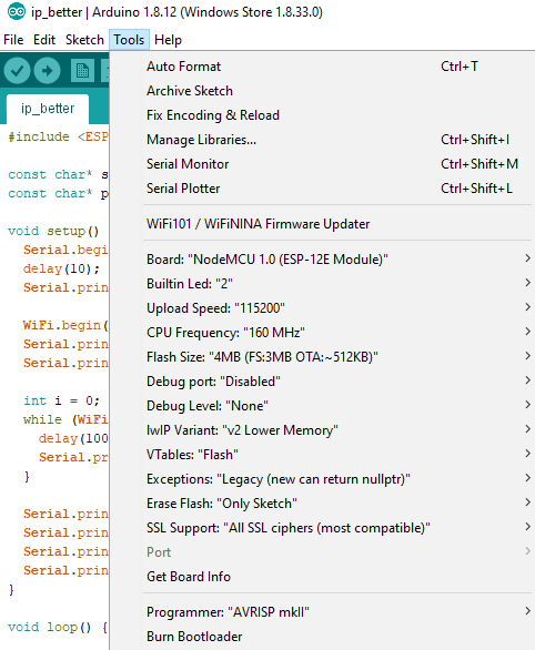
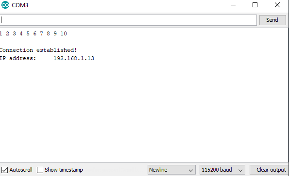
http://arduino.esp8266.com/stable/package_esp8266com_index.jsonLoading the software is dependent on the type of ESP8266 module that you are using. the one used in this project was loaded up with the following settings in Arduino IDE. we start by connecting the ESP8266 to the computer with a micro USB cable and downloading the appropriate libraries for flashing. Tools -> Board -> NodeMCU 1.0 (ESP-12E Module) Tools -> Flash Size -> 4M (3M SPIFFS) Tools -> CPU Frequency -> 160 Mhz Tools -> Upload Speed -> 115200 the led software communicates wirelessly through the ESP8266 module so we must first obtain the IP address that the router assigns to the device. we do so by loading up a basic IP ping program and providing it the SSN and PASSWORD combo for your particular router. we then open up the serial monitor ensuring that the upload speed is specified and matches the one chosen above. the program should now return the IP address if it does not then simply hold the RST button on the ESP8266 and the program should start.
Apply the following settings under
Arduino IDE > Tools
red/white wires connect to PSU the others 3 to the breadboard
110V must be selected on the PSU (if you live in NA that is..)
Next we are going to load up the led software and paste in the IP address that we just obtained from the previous step as well as some other variables.
// Set to the number of LEDs in your LED strip
#define NUM_LEDS 256
// Maximum number of packets to hold in the buffer. Don't change this.
#define BUFFER_LEN 1024
// Toggles FPS output (1 = print FPS over serial, 0 = disable output)
#define PRINT_FPS 1

//NeoPixelBus settings
const uint8_t PixelPin = 3;  // make sure to set this to the correct pin, ignored for Esp8266(set to 3 by default for DMA)

// Wifi and socket settings
const char* ssid     = "SSID";		// Enter your SSID here
const char* password = "PSWRD";		// Enter your PSWRD
unsigned int localPort = 7777;
char packetBuffer[BUFFER_LEN];

// LED strip
NeoPixelBus ledstrip(NUM_LEDS, PixelPin);

WiFiUDP port;

// Network information
// IP must match the IP in config.py in python folder
IPAddress ip(192, 168, 1, 13);		// Enter your IP must match IP returned from previous program
// Set gateway to your router's gateway
IPAddress gateway(192, 168, 1, 1);		// this can be obtained from the command prompt by running "ipconfig"
IPAddress subnet(255, 255, 255, 0);

void setup() {
	Serial.begin(115200);
	WiFi.config(ip, gateway, subnet);
	WiFi.begin(ssid, password);
	Serial.println("");
	// Connect to wifi and print the IP address over serial
	while (WiFi.status() != WL_CONNECTED) {
		delay(500);
		Serial.print(".");
	}
	Serial.println("");
	Serial.print("Connected to ");
	Serial.println(ssid);
	Serial.print("IP address: ");
	Serial.println(WiFi.localIP());
	port.begin(localPort);
	ledstrip.Begin();//Begin output
	ledstrip.Show();//Clear the strip for use
}

uint8_t N = 0;
#if PRINT_FPS
	uint16_t fpsCounter = 0;
	uint32_t secondTimer = 0;
#endif

void loop() {
	// Read data over socket
	int packetSize = port.parsePacket();
	// If packets have been received, interpret the command
	if (packetSize) {
		int len = port.read(packetBuffer, BUFFER_LEN);
		for(int i = 0; i < len; i+=4) {
			packetBuffer[len] = 0;
			N = packetBuffer[i];
			RgbColor pixel((uint8_t)packetBuffer[i+1], (uint8_t)packetBuffer[i+2], (uint8_t)packetBuffer[i+3]);
			ledstrip.SetPixelColor(N, pixel);
		}
		ledstrip.Show();
		#if PRINT_FPS
			fpsCounter++;
			Serial.print("/");//Monitors connection(shows jumps/jitters in packets)
		#endif
	}
	#if PRINT_FPS
		if (millis() - secondTimer >= 1000U) {
			secondTimer = millis();
			Serial.printf("FPS: %d\n", fpsCounter);
			fpsCounter = 0;
		}
	#endif
}